from Rob Legg Yachts | |||||
|
|
|
|
|
||
Episode 1: Designing the RL28
 We wanted maximum facilities in the accommodation in a restricted hull space so that space had to be carefully utilised and the best way to do this was to work on a full size drawings, so on a wall under the house we drew a full size profile and set out what we wanted to fit in. At first it seemed that getting full head room was not going to be practical, no matter which way we drew it either the hull looked too deep and clumsy, or the cabin sides looked too high. Finally we came up with a solution, we would create an optical illusion by giving the deck a pronounced reverse sheer, but at the same time make the hull to deck join a slight concave line and as this would stand out in a dark colour the space between the deck and gunwale would disappear, this also gave us more usable room inside.

Every thing on a sailing boat is a compromise, narrow beam had been forced on us by the road rules, so to compensate a smaller than usual
rig was needed together with a reasonable amount of ballast to make the boat positively self righting. To make the retractable keel
manageable half the required weight would have to be in the hull, and the best way seemed to be making the hull bottom solid up to the
interior floor level , this also would create an extremely strong base for the centre board I redrew the lines drawings several times
to achieve the desired amount of buoyancy under the water line and also achieve enough volume under the floor for the amount of ballast.
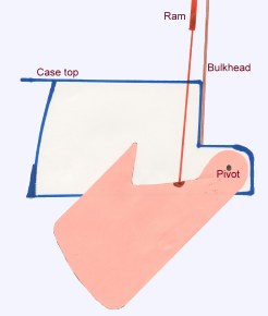
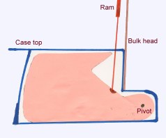
At first the floor space forward looked impossibly small, but after doing a mock up of the toilet- shower compartment it was adequate as long as there was elbow room, and hopefully no one would have to spend much time in there. An important decision had to be made regarding the centre board.
11,000 grey cast iron was chosen for the keel. I had used it on the 24 and had found that, provided new Pig iron was used, it was ideal. It was easy to work with, was resistant to corrosion, and Tar epoxy paint held well on it. It also appeared that there was very little electrolysis between it and good grades of stainless steel. Go back to Index | Go on to Next Episode |