from Rob Legg Yachts | |||||
|
|
|
|
|||
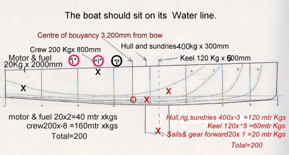
Part 2With a line drawing complete, now is the time to check that the boat will in fact sit on its designed waterline. This will also have an influence on the positioning of the rig and keel.
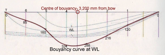
First we must find the centre of buoyancy of the hull! This can be done from our original displacement calculations by drawing a displacement curve and finding its centre by drawing out its profile on a piece stiff cardboard, cutting it out, and finding its balance point. The scale doesn’t matter, the result will be the same.
 The centre of buoyancy is 3,200 mm from the bow. We now have a starting point from which to distribute our weights. Ideally the heaviest weights should be kept close to the centre of the boat to prevent any pendulum or hobbyhorse effect.  Note. All distances taken from the centre of buoyancy. Drawing not to scale. Some notes from the weights distribution drawing.
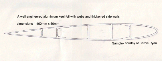
In recent years there has been a lot of work done on foils, and we couldn’t even consider using anything other than a recognised section; the efficiency is so much greater than the old idea of just a rounded leading edge and a tapered trailing edge. I have chosen an available aluminium section of ideal dimensions, namely, 460mm wide and 50mm thick. It has four webs and it is most convenient because the cross sectional area is just over 100 square cm, and that amounts to nearly two kilograms of lead for every centimetre of length, so in that case filling the bottom of our keel for a distance of 600mm will give us 120Kg, and the centre of gravity will be 300mm from the bottom. I doubt that pouring molten lead directly in to an aluminium extrusion would work, and there is the problem of electrolysis, so lead shot pored in to an epoxy mix would be best, although it would raise the ballast another 100+ mm.  For those interested there is a lot of technical information on foils available on the internet, but the results from a lot of the studies becomes rather confusing, because one can not reproduce on a boat the conditions under which the results were obtained. I have always liked the convenience of a swing keel, but if you are chasing performance there are too many problems, and I would really prefer a lift keel with most of the ballast in a bulb, as it would in this case lower the centre of gravity, by 300mm, thereby increasing the safety factor and allow us to decrease the actual ballast weight.
Have your say !A decision must be made:
(A) A vertical lift keel that can be fully housed. Let us know which you would prefer. Add a message to the discussion forum on the new boat with your preferences. Go back to Previous Episode | Go back to Index | Go on to Next Episode |


